

Last time we learned how to draw a text on the HTML5 canvas element using javascript. Today we will create a design of rectangles on the second canvas.
Let’s first see the output of the text created in last session.
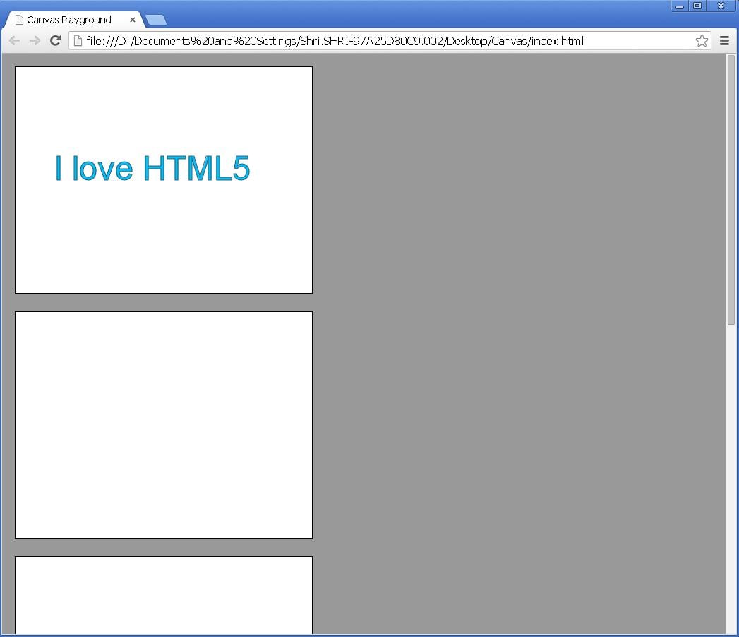
fig 1
This text was drawn on the first canvas.
Let’s go to the second canvas. The design that we will draw will be somewhat like shown in the figure 2 below:

fig 2
Now let’s create the design in canvas2 step by step.
- Open the “canvas.js” file which is in the “Canvas” folder on desktop.
- Write the following code in the “makeCanvas()” function, below the code for the text “I love HTML5”.
- Firstly using the code
//1 - Get Object var canvas2=document.getElementById("canvas2"); var ctx2=canvas2.getContext('2d');we get the object, “canvas2” and it’s context.
- Secondly we set some properties for the shape using the following code:
//2 - Set Properties ctx2.fillStyle="#FF0000"; ctx2.strokeStyle="#000000"; ctx2.lineWidth=10;
- Here, ctx2.fillStyle=”#FF0000″; fills the square with red colour.ctx2.strokeStyle=”#000000″; gives a border of black colour to the red square. And ctx2.lineWidth=10; gives a width of 10 pixels to the black border.
- After setting the properties the third step is to draw the square. Code for it is as follows:
//3 - draw square ctx2.fillRect(45,5,135,135); ctx2.strokeRect(45,5,135,135);
- Here, fillRect() is the inbuilt function to draw a rectangle. Parameters of fillRect() function consist of x and y positioning co-ordinates and width and height of the rectangle respectively. When width and height is same, it will form a square.
- The output till fillRect() function is shown below:
- Now, when you write the further line of code i.e.
ctx2.strokeRect(45,5,135,135);
the output will look as shown below:
- Here, strokeRect() function has same parameters as the fillRect() function and it gives a black colour border to the red coloured square. The border is black because of the “strokeStyle” property and it gets it’s width from the “lineWidth” property.If you increase the value of the “lineWidth” property, its width will increase overriding the red square.
- Now, let’s move to the top right square. Code for it is shown below:
- The square we had drawn first had “red” colour, but the square next to it has “grey” colour. So we need to again set the property of “grey” colour for this square.
- The “grey” colour is set using “fillStyle” property.
- This “grey” coloured square has no border, so no stroke is needed.
- The square is drawn using “fillRect()” function with x co-ordinate as 200 pixels, y co-ordinate as 0 pixels and width and height as 135 pixels.
- The output is shown below:
- Next, you can see a one more grey coloured square below the red coloured square in figure 2.
You can draw it using fillRect() function as before with required parameters. The code is shown below: - Here, there is no need to set the “fillStyle” property for “grey” colour, because it is already set during the previous square.
- We need to only draw the square with function fillRect() having parameters 45 and 150 as x and y co-ordinates and 135 and 135 as width and height respectively.
- The output is shown below:
- Now a last square which is same as that of the first one is remaining. Repeat the code for the first square only with different x and y co-ordinates in fillRect() and strokeRect() functions as shown below:
////Second Canvas - Squares ////

	//Top Left Rectangle

	//1 - Get Object
	var canvas2=document.getElementById("canvas2");
	var ctx2=canvas2.getContext('2d');

	//2 - Set Properties
	ctx2.fillStyle="#FF0000";
	ctx2.strokeStyle="#000000";
	ctx2.lineWidth=10;

	//3 - draw square
	ctx2.fillRect(45,5,135,135);
	ctx2.strokeRect(45,5,135,135);
Explanation of above code:
This code draws the top left square as shown in figure 2 above.
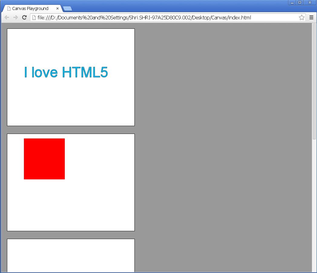
fig 3
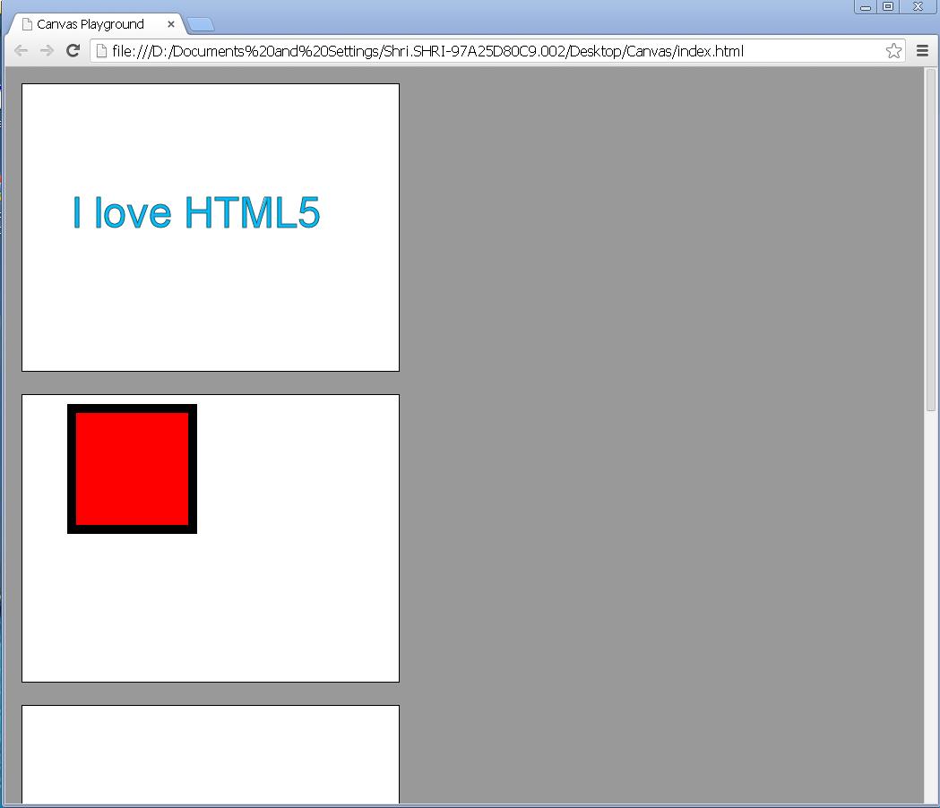
fig 4
//Top Right Rectangle(no stroke)

	//2 - Set Properties
	ctx2.fillStyle="#666666";

	//3 - draw square
	ctx2.fillRect(200,0,135,135);
Explanation of the above code:
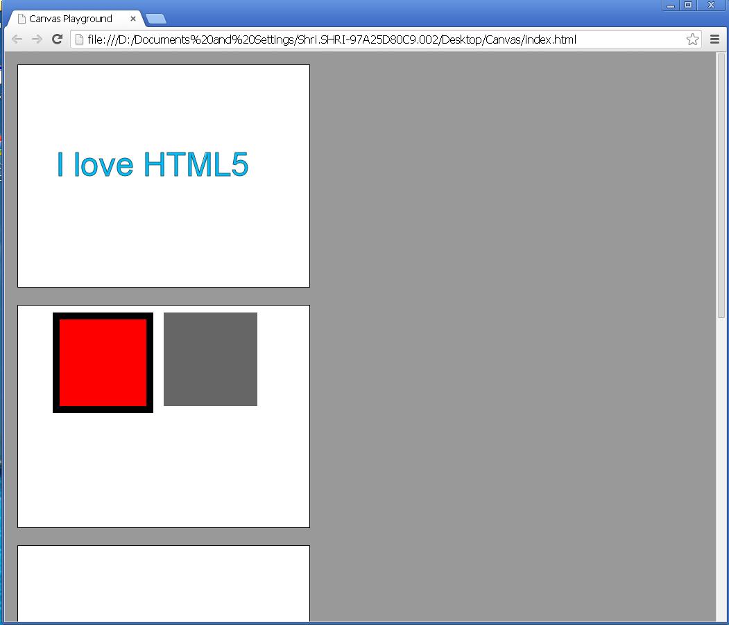
fig 5
//Bottom Left Rectangle (no stroke)

	//3 draw square
	ctx2.fillRect(45,150,135,135);
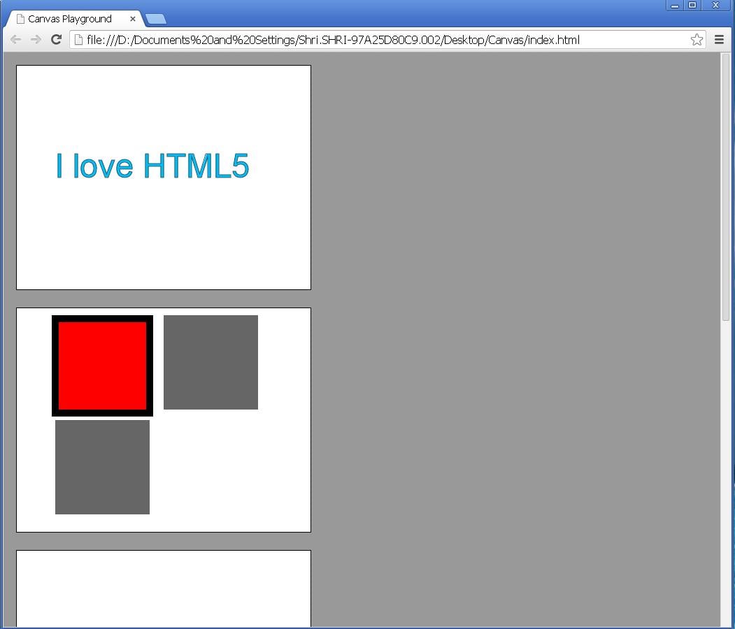
fig 6
//Bottom Right Rectangle

	//2 - Set Properties
	ctx2.fillStyle="#FF0000";
	ctx2.strokeStyle="#000000";
	ctx2.lineWidth=10;

	//3 - draw square
	ctx2.fillRect(200,150,135,135);
	ctx2.strokeRect(200,150,135,135);
The output is shown below: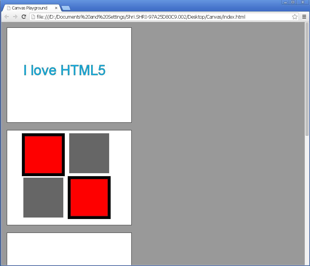
fig 7
Here we finished with our square design. In the next session we will learn to draw lines and join them to make any figure out of it.
